
I must admit – the LianLi O11 Dynamic Evo is a pretty good computercase. It is quite expensive, yes, but nevertheless, it has good build-quality, some exceptional new and neat ideas (thanks Der8auer) and it is fun to work in. Sure, some people hate it, because they see it as cheat-code to make watercooled systems look cooler than they probably are while spending less effort getting there, especially with distroplates. This might by partially true, but so what? Haters gonna hate…
Some upgrade-parts that not everybody needs are also available, like vertical (and upright) gpu-brackets and such. However, the Upgrade that is most interesting, is the front-I/O-bracket which – despite it’s name – is mounted on the top side. When using this, you’ll end up having an empty shell where the I/O-hardware has been sitting in. While it is basically waste from now on, I always had in mind to use it for some mod, like a character-display for status-things, or a LED-bar for the same porpose. While thinking about this, I missed another item much more on current PCs, and this is a cardreader. Occasionally i shoot photos with my mirrorless cam flash images for raspberry pis or install some router OS to a CF-Card for diskless router-appliances. Modern PC-cases don’t feature any external accessable 3.5″ or 5.25″ drive bays any more, where a cardreader would have naturally go to in the past. So I made my own…
First of we need to decide on some parts, which sounds easier as it is. I personally couldn’t care less about the famous format-wars of the ’90s and 2000s (of flash-media-formats in this regard). The de-facto standard is now SD-Card and it’s numerous high-density-successors in the sizes „normal“ and „micro(sd)“. The only other useful flash-card you might want to use is CF-card, because it is pin-compatible to IDE, which is interesting for retro-computing applications. Thus said, focussing on SD and CF makes much more sense, than some random „52-in-1-cardreader“. The driving chip might even be the same as in SD-only cardreaders, but we are space-constrained here, and no one uses the rest of this crap anyways.
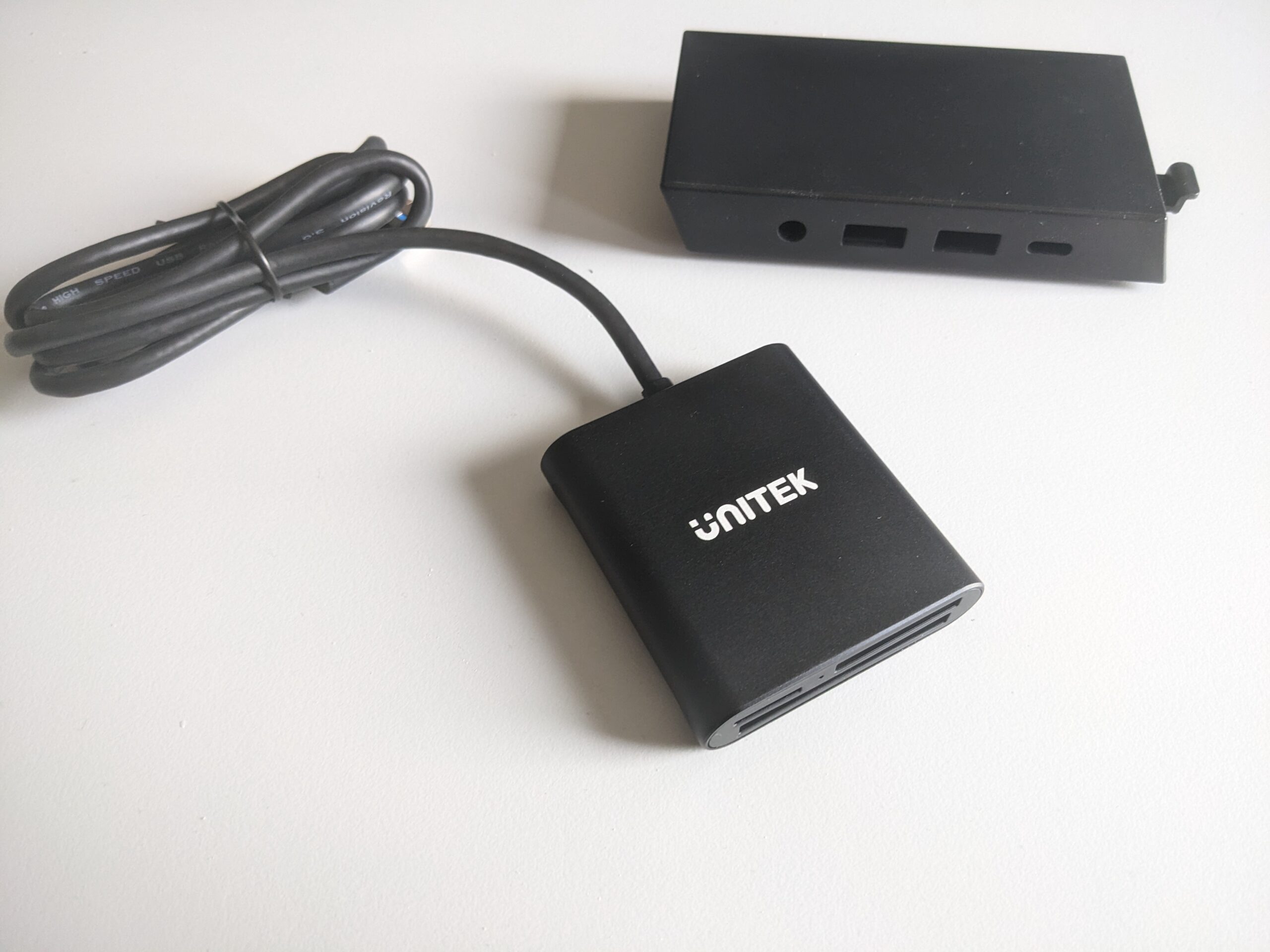
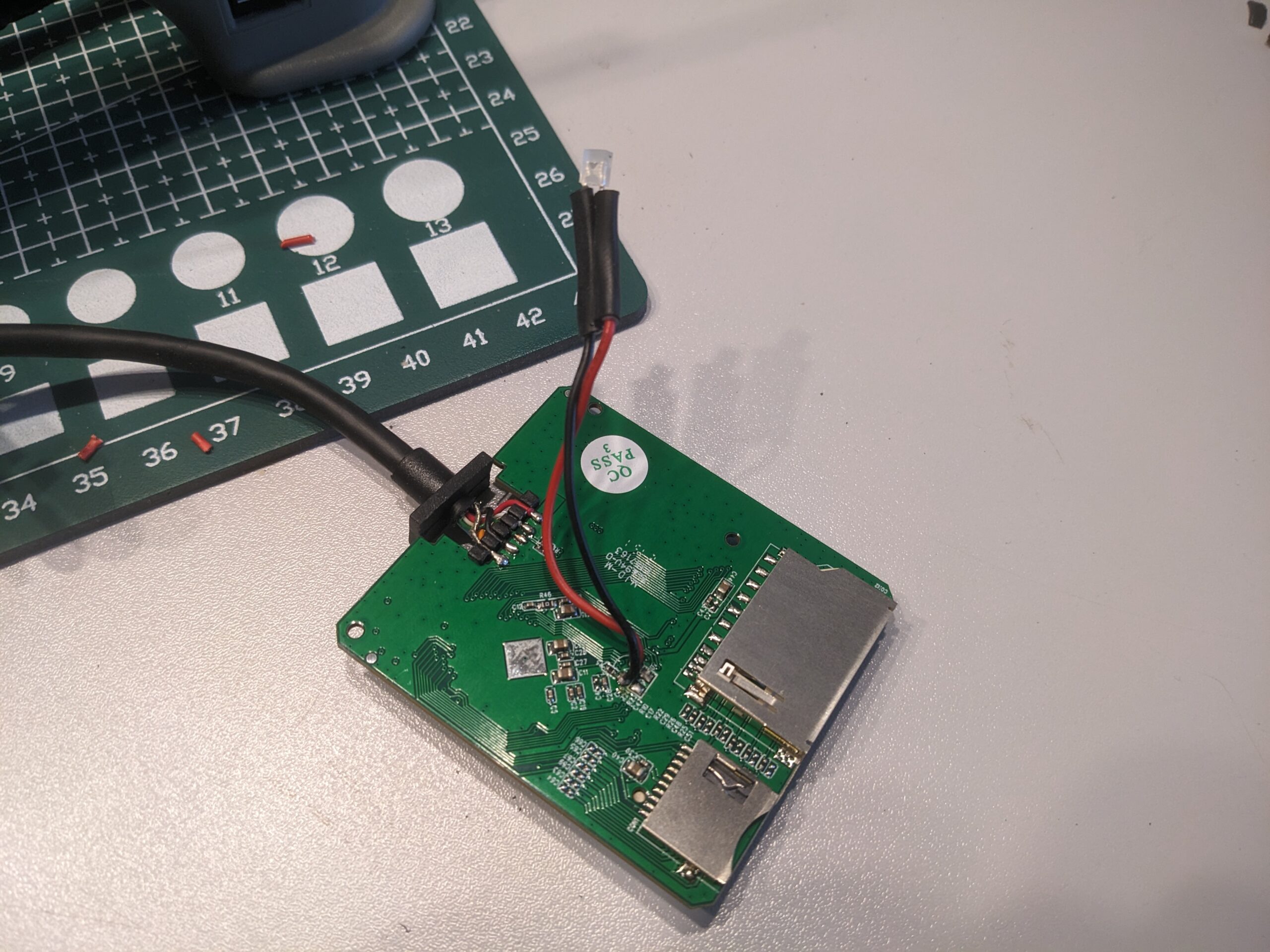
Leftover Front-I/O-casing and SD/µSD/CF Cardreader with 1.2m cable terminating to USB-A
Connectionwise you can go with internal USB-headers (less clutter, most likely cleaner) or plain normal „external“ USB (with USB-A or USB-C). For internal models you should have a spare USB3-Header. For transferring more than a few snapshots, like raw-images or whole partitions, USB2 isn’t cutting it anymore. USB3 is the way to go. I haven’t got spare USB3-Headers left, so i went with a USB-A-Plug. On cardreaders for internal use, you have the better baseline to choose from: Basically all models have all ports on the same side of the PCB, and the cable is usually long enough. On external cardreaders you often have to sort out models with slots on more than one side and with short pigtail-cables (however, the latter can of course work with extension-cords). I was lucky to find one with a long enough cable (1.2m), but i felt that this was one of the very few ones. Most cardreaders have short pigtail-cables attached. It is quite useless to list Amazon-links to the one i bought, because they change as quick as the day cycles, you’ll have to basically guess which one fits best, so did I. I paid around 20€ for mine.
Compatibilitywise it basically doesn’t matter. You can expect all cardreaders in the pricerange from 10 to 50$ to be basically identical, because it it all handled by a SOC from realtek or comparable. Most models only differ in color, material, branding or other cosmetics like a status-LED, sometimes not even this.
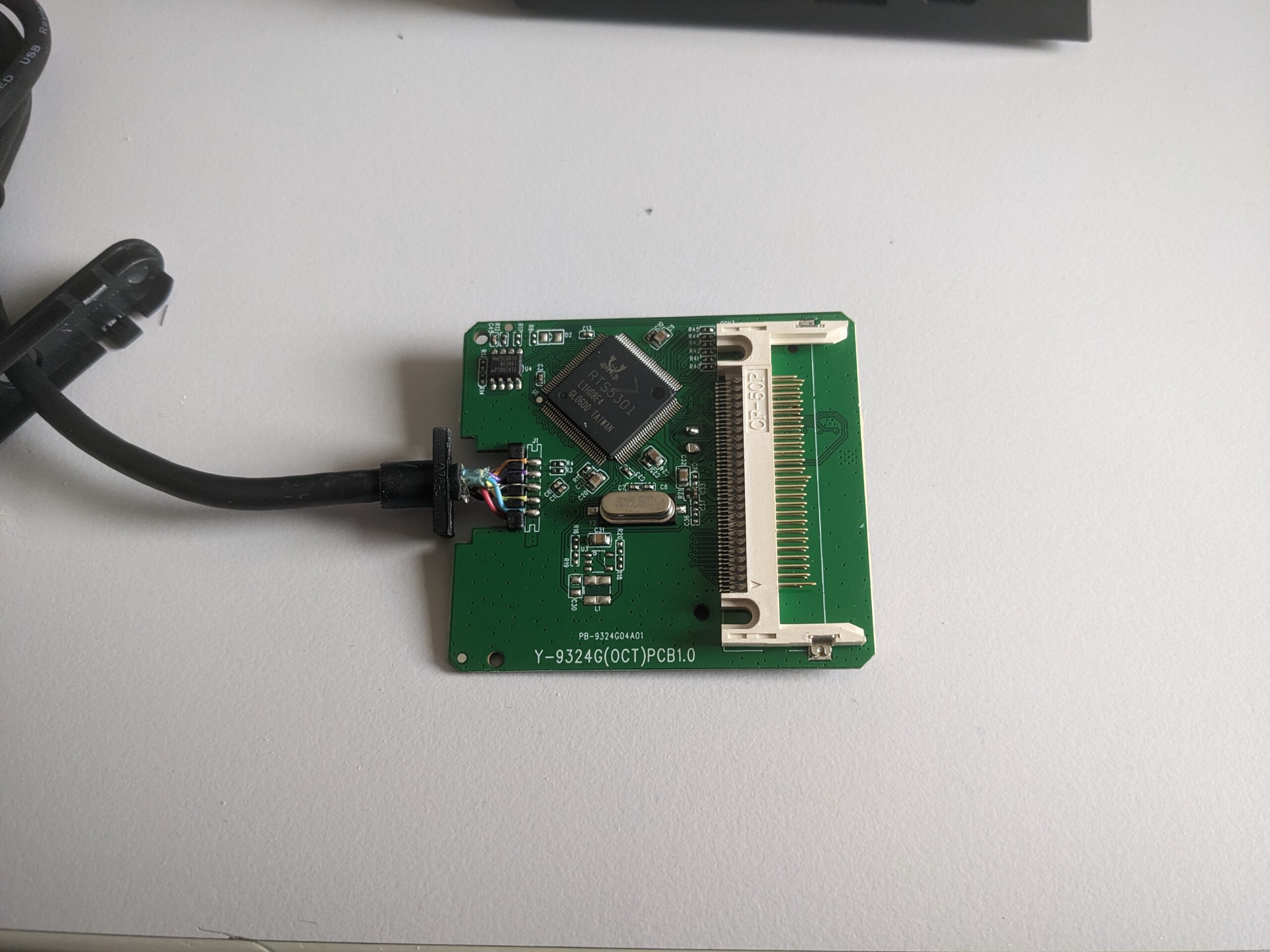
Cardreader stripped down
The cardreader I bought consists of 2 plastic faceplates (of which one also acts as stop-block for the strain-relief of the cable), an anodized, black aluminium profile and the PCB of course. Nothing special here so far.
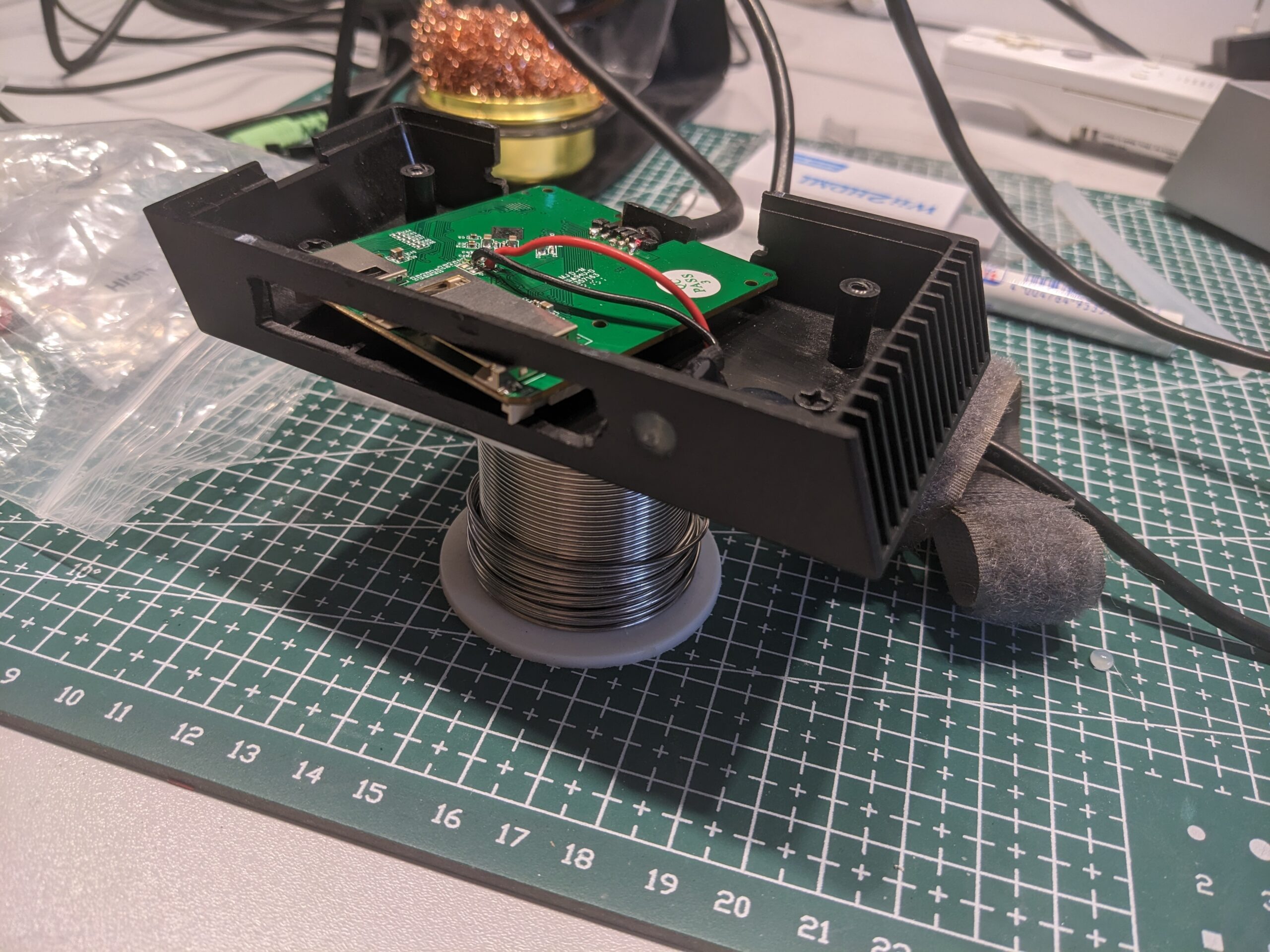
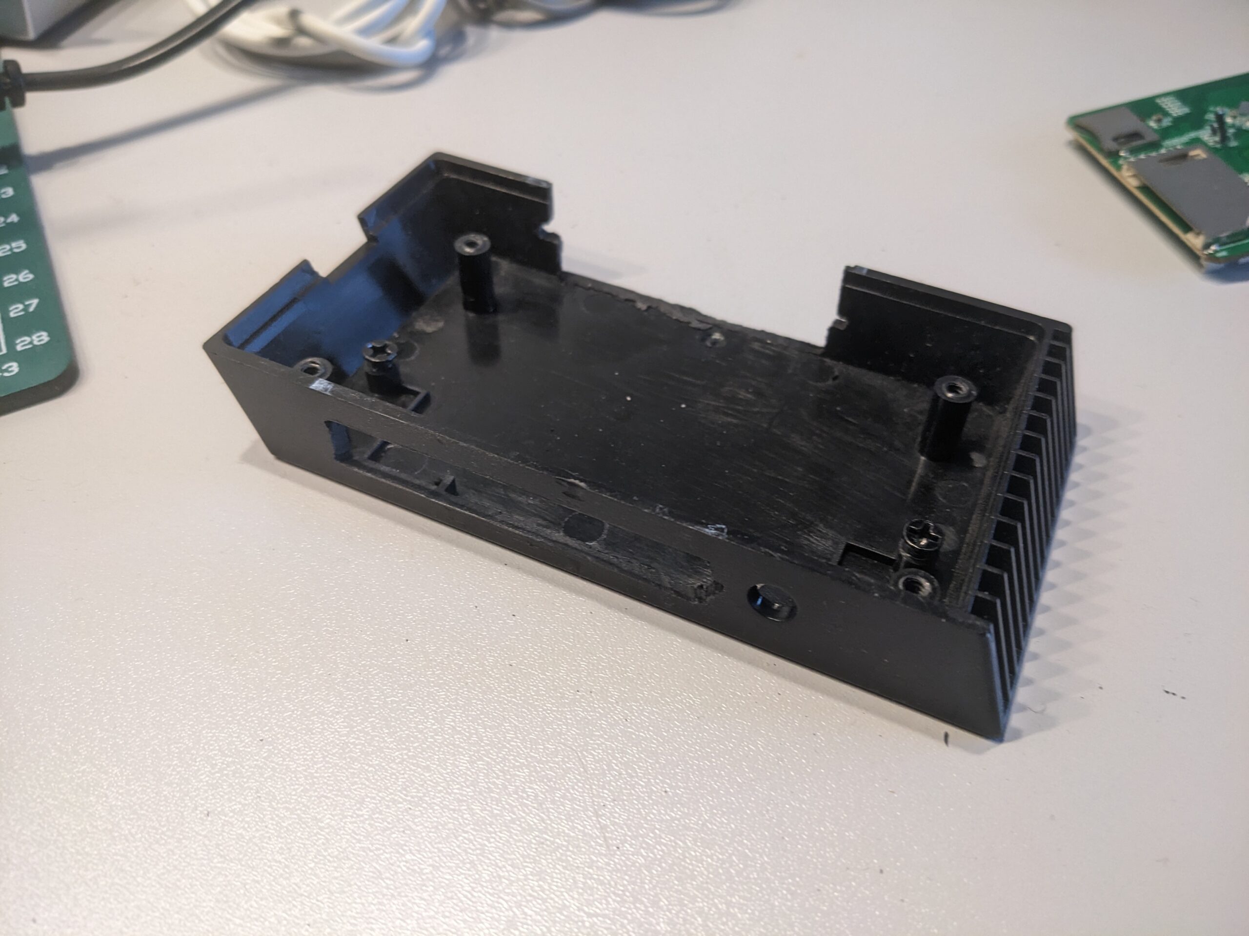 The first task would be to modify the stock front-I/O-Housing of the O11D-Evo. To be honest, I grabbed my dremel any just eyeballed it. On the front i widened all USB-cutouts to a bigger one, and removed the center-section on the backside. a small slit as a rail for the PCB was also cut. I left all tabs on the inside present, because on some of them the PCB could rest in a position that was almost spot-on. The front-cutout was slighly too wide, but i fixed that later. For now it looked promising, even slightly ugly. however: function over form was the goal here.
Relocated LED
As soon i realized, that the LED was a throughhole-LED, and not SMD, and therefore easy to relocate with a soldering-iron and a few centimeters of cable, I did just this: Adding a bit of cable-slack. The case has a round opening (in stock-configuration for a 3.5mm headphone-jack), which was useless now, but the LED gave an interesting opportunity to fill this gap (pun intended).
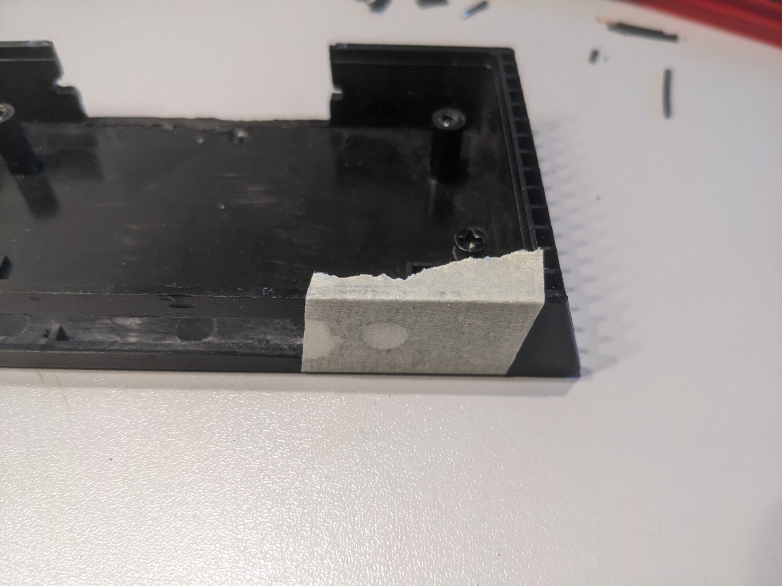
Painters-Tape for the texture
I first taped of the hole from the outside with painters-tape. This tape has a very similar texture than the case itself. After that i filled the hole with (a very generous amount of) hotglue, and sticked the LED in. The hotglue acts as simple diffuser, and the finished product really looks like as if it has to be this way from the beginning.
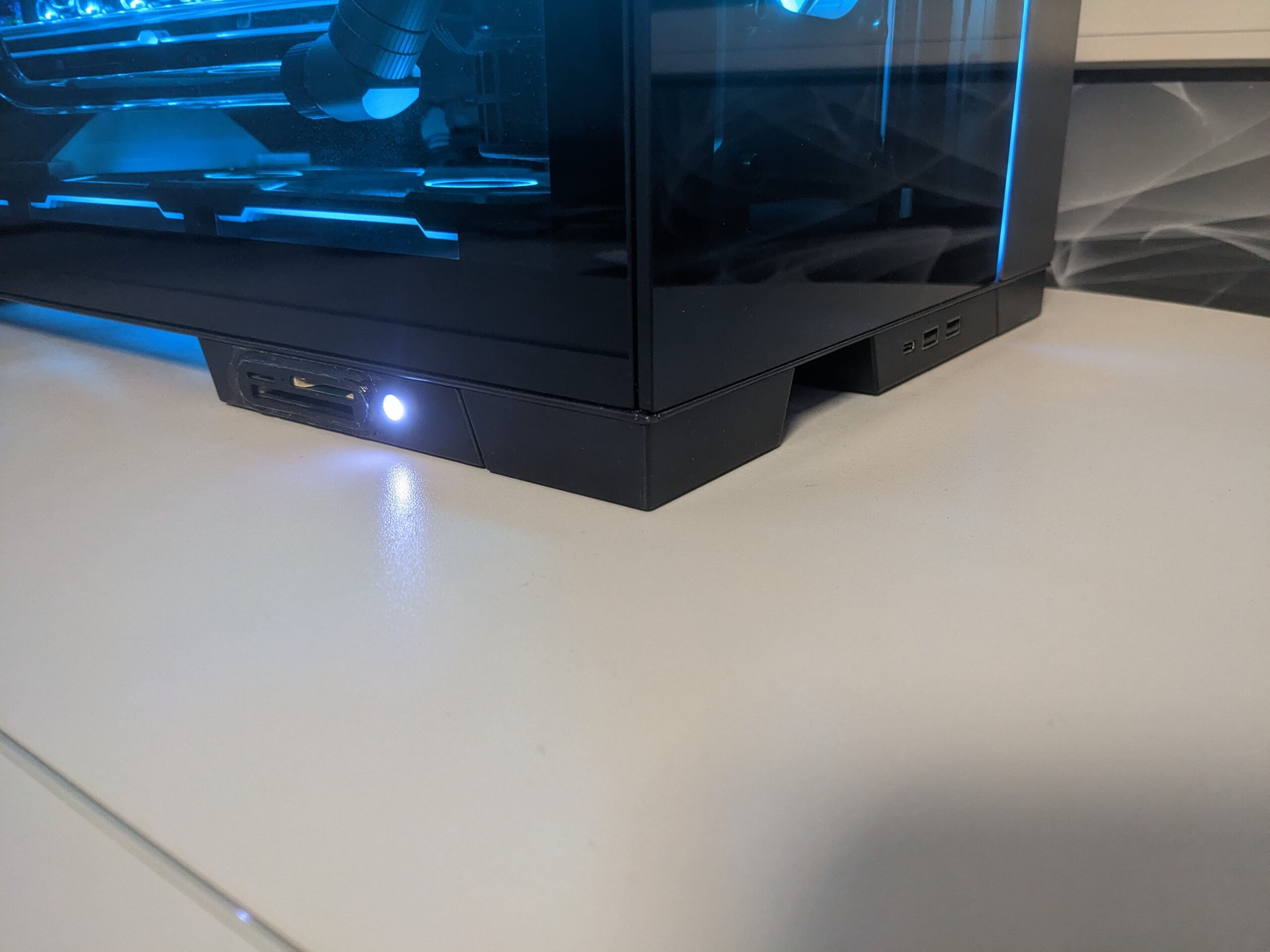
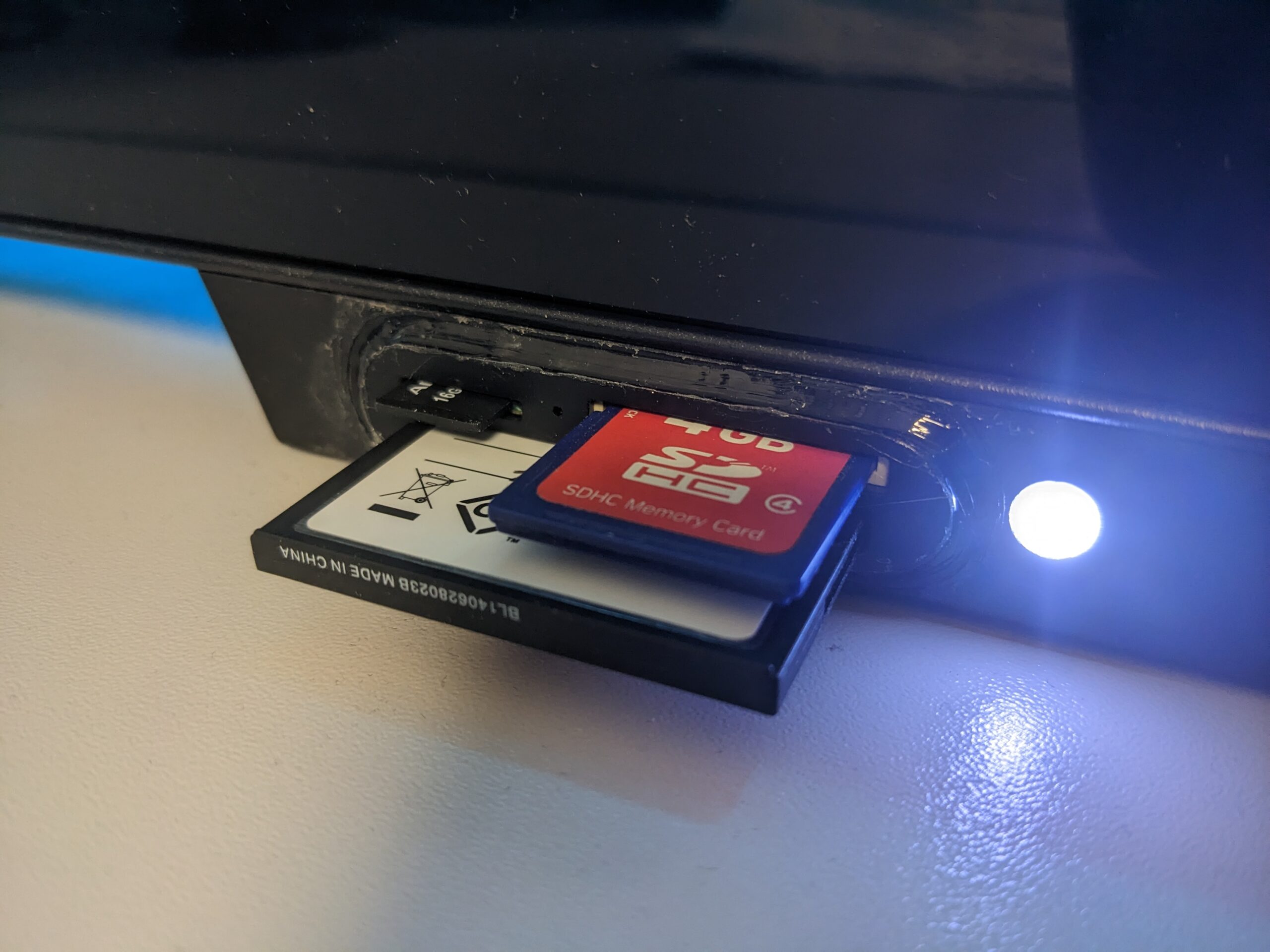
Hotglued LED in the cutout of the former audio-jack

…and with lights on (luckily the included LED is white and not red….)
Next i placed some leftover packing-foam into the shell and fixed it in place with some dabs of hotglue. The foam had just the right height, so that the PCB can rest on it with light pressure in the perfect position. After that, I positioned the PCB in the center (on the y-/depth-axis) and used another very generous amount of hotglue to fix the board permanently in place. Usually I don’t use hotglue at all, or at least very rarely, but for this project it just wasn’t worth it to construct and 3d-print something, when the same goal can be archieved with hotglue in 5 minutes.
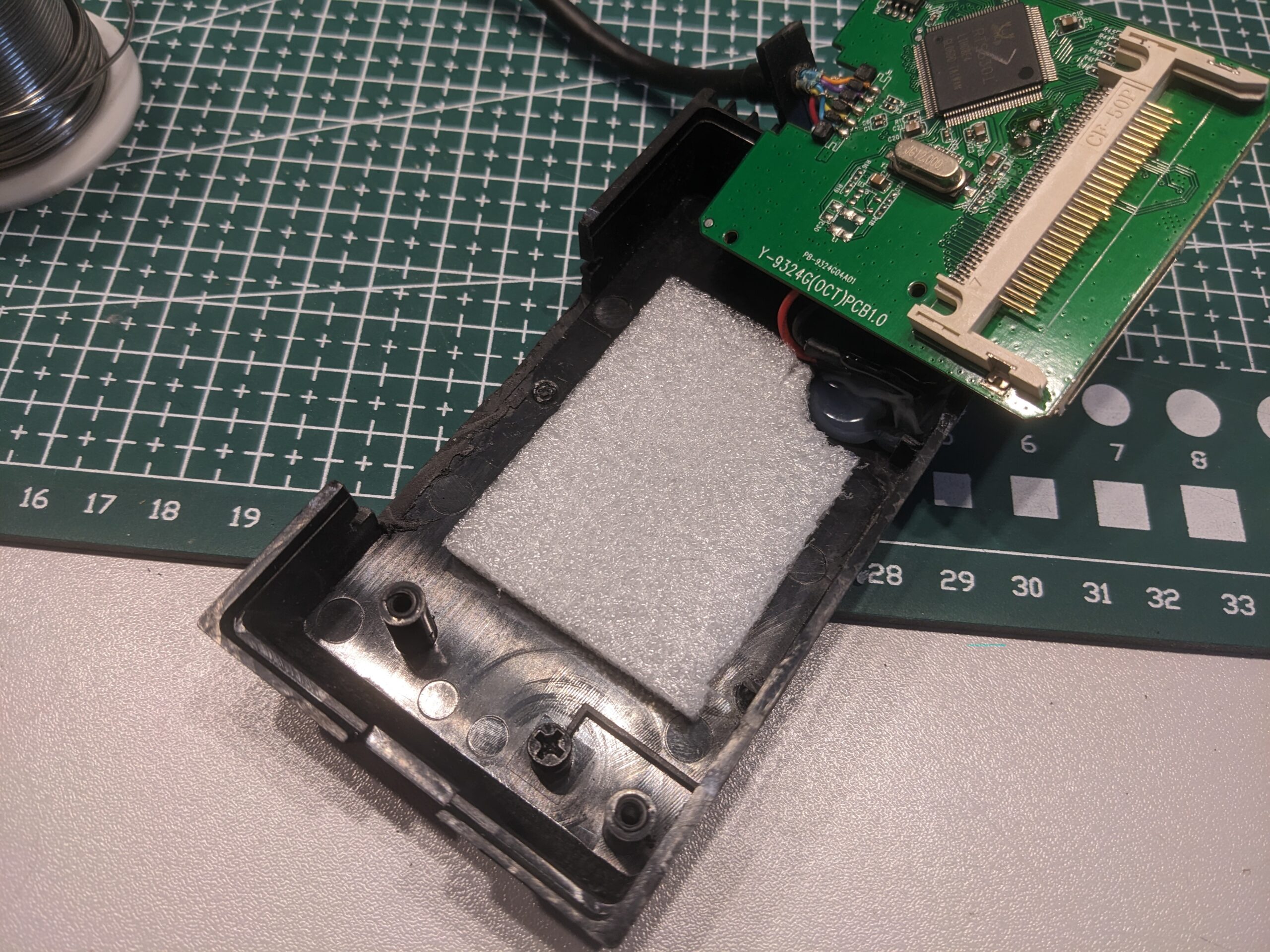
After this picture i cutted the front of the foam even shorter , so that it doesn’t interfere with the Pins of the CF-Reader and then glued in the board
While i was already going to cut the plastic-part from the cable, i realized, that if I remove just the tabs on the inside, and stick it on with black hotglue (which i had on hand luckily), the faceplate not only fills the backside almost completely, but it will again act as a proper strain-relief for the cable, because the PCB has basically the same depth as the shell.

Back side glued on.
Even better was, that the same trick was possible with the frontplate. Everything had just exactly the right dimensions. A positive side-effect was that it now doesn’t look as nearly as hacky as before, and the frontcover actively prevents any flash-cards from beeing able to be inserted incorrectly or sideways. With the black hotglue-sticks in the gun and some light, continuous motion, you can get almost the same results as caulking your bathroom-tiles.
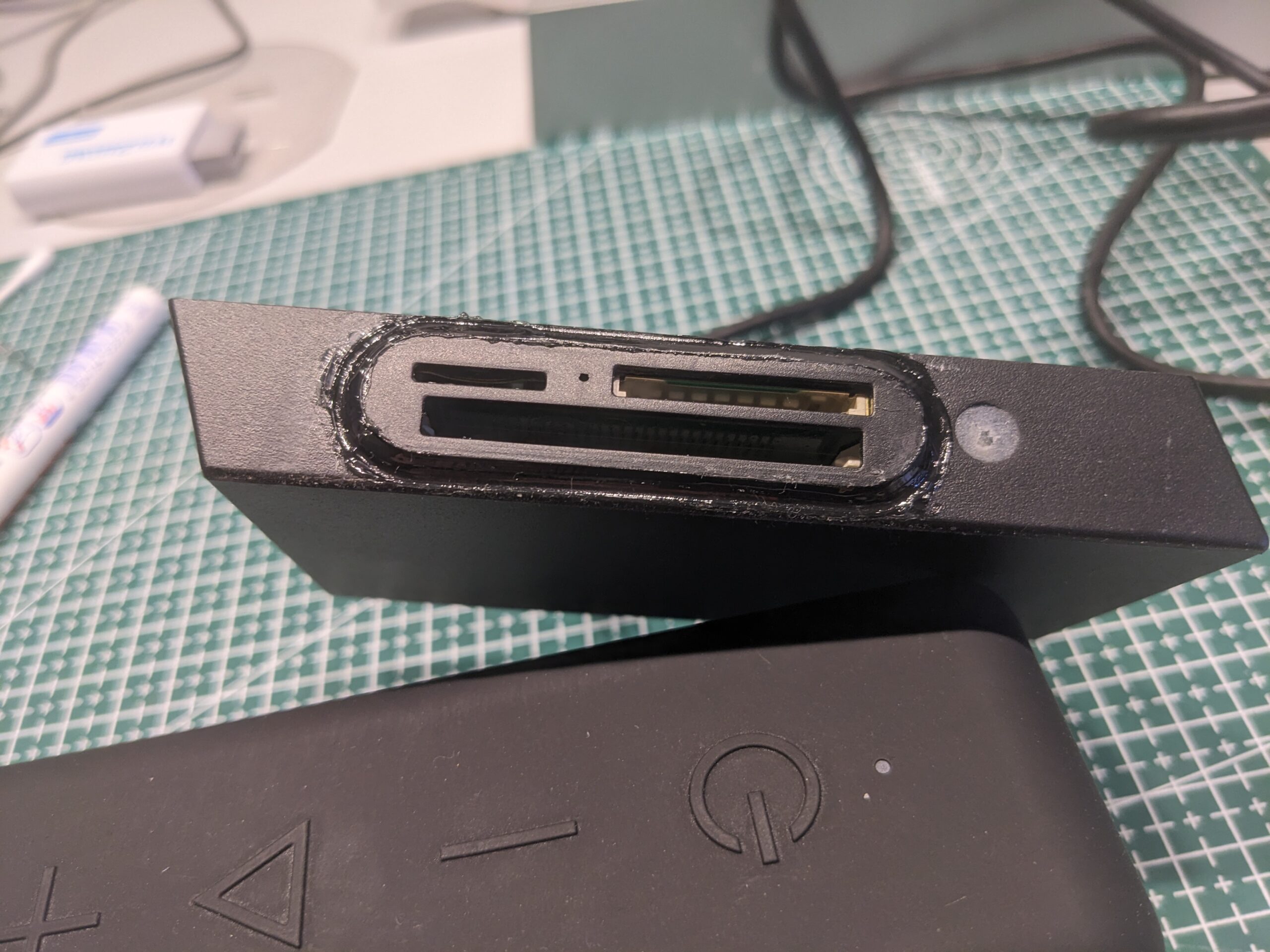
As well as the front
Even tough it looks slightly messy on camera, the effect is much more suttle in reality.
Pretty even light-diffusion for hotglue
All in all, I am pretty happy with the endresult. I routed the cable underneath the case to the back and then to the I/O-Section of the mainboard, but this is basically invisible from the outside, and the cardreader looks like as if it belongs there. All work combined, this whole thing did not exceed 2 hours, and for that, this is a result i can happily live with.
have fun,
-zeus